1. Cortex Microcontroller and VEXnet Joystick Pairing Procedure:
- The Joystick must first be paired to the Cortex Microcontroller before they will work using the VEXnet Keys. Pairing requires a USB A-A Cable and a VEX 7.2V Battery. This process must be completed each time you use a Joystick or Cortex with a new mate. A Joystick can only communicate with a Cortex that it has been paired with. During the Pairing Process, the ID from the Cortex is transferred to the Joystick; thus mating the two units together.
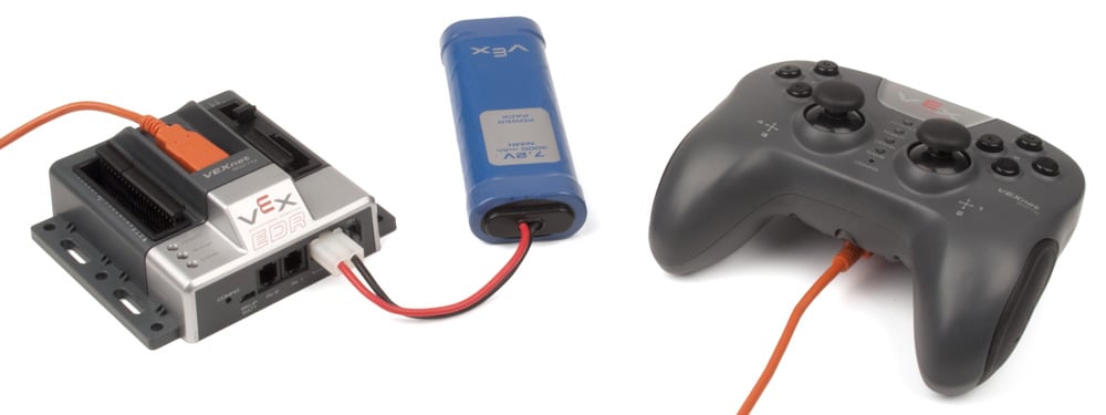
- Start with the Cortex and Joystick turned OFF.
- Connect the Cortex to the Joystick using a USB A-A Cable.
- Connect the 7.2V Robot Battery to the Cortex.
- Power up only the Cortex.
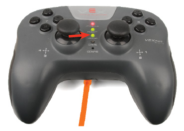
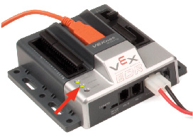
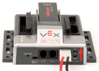
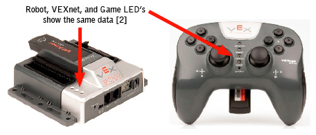
- A successful tether is indicated by a Solid Green VEXnet LED on both the Joystick and the Cortex (See Figure Below).
- The Solid Green VEXnet LED must remain ON on both units at the same time for a minimum of 5 seconds.
- Disregard the other LEDs as you are only interested in the VEXnet LED.
- Pairing may take up to one minute to complete.
- Once the units have finished pairing, turn OFF the Cortex.
- Disconnect the USB A-A Cable from both units.
- Disconnect the 7.2V Robot Battery from the Cortex.
2. Basic connections; batteries, microcontroller, Joysticks and (2) VEXnet keys.
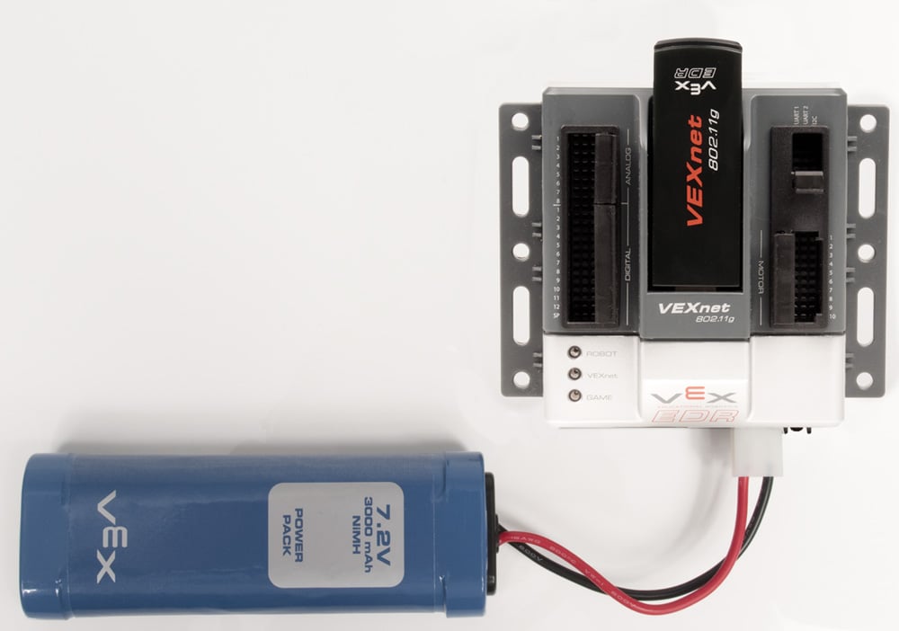
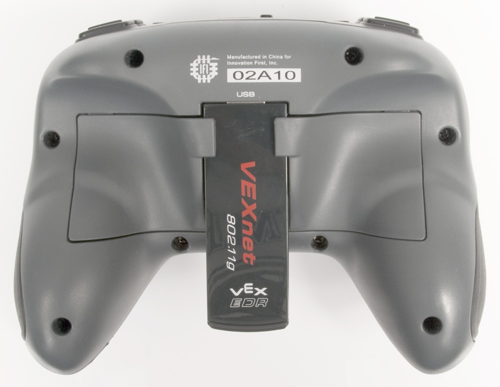
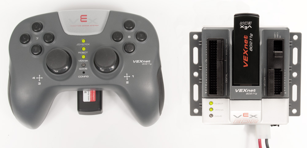
- Attach a 7.2v battery and a VEXnet 802.11g key to the Cortex as shown above.
- Install six identical batteries as shown. Use Alkaline, Ni-Cad or Ni-MH type batteries, but DO NOT mix different kinds of batteries. Charge rechargeable batteries only with a quality charger designed for your battery type.
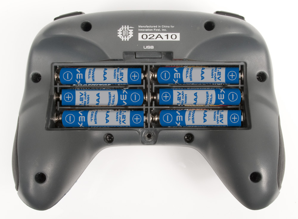
- Reinstall the battery cover (insert the two tabs of the battery cover first along the back edge of the battery cover to aid in installation) and then tighten the cover screw. Then add the VEXnet 802.11g key as shown.
- You can also power your Joystick directly from a standard wall outlet using the Joystick Power Adapter (276-1710). Simply plug this cable into your Joystick’s PROGRAM/FACTORY port and you can operate your Joystick without the use of batteries. Please note: when using the Joystick Power Adapter, it is not necessary to turn your Joystick ON. Also, the JOYSTICK/POWER LED can be ignored.
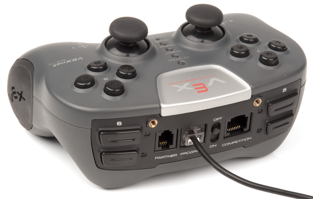
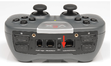
- Turn on the Cortex and Joystick by setting the power switches to ON as shown in the two pictures below.
- A valid link is shown below. The VEXnet LED will be blinking fast green on both the Cortex and Joystick. The VEXnet light is the only LED that determines a valid link. It usually takes 5 to 10 seconds to successfully establish a link. Once the units are linked, the Robot and Joystick LED Indicators will show the battery levels in their respective unit. A green Robot or Joystick LED indicates that their respective batteries are fully charged batteries. As the battery levels decrease, these LEDs will change to yellow and then red.
- If the units fail to establish the VEXnet link after 30 seconds, turn them both OFF and then back ON. If they still fail to link up, refer to the Troubleshooting Flowchart in section 7.
3. Basic Configuration
A few examples of the Default Code that is preloaded onto the Cortex Microcontroller are shown below. For complete details on the Default Code, refer to Section 4. Please note: The default code for the Cortex Microcontroller varies from that of the PIC Microcontroller. Please review and follow the tables in this document to ensure your robot behaves in the manner you wish.
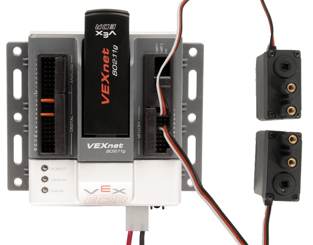
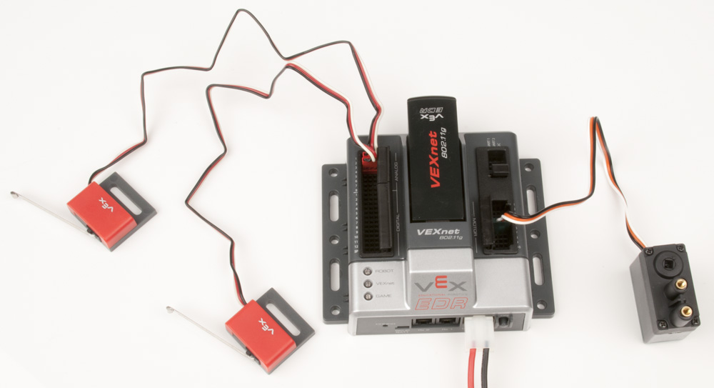
- Add motors and test. The following picture shows two VEX 3-Wire Motors plugged into Motor Port 2 and Motor Port 5. With the Default Code, pushing Joystick Channel 3 up will cause Motor 2 to turn clockwise. Pushing Joystick Channel 2 up will cause Motor 5 to turn counterclockwise.

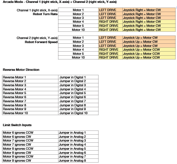
- Motor Reversing: The Default Code allows jumpers or switches to be installed in the Digital Ports to invert the motor direction. This is useful to correct the direction of motors without changing code, or when using a switch to reverse a motor if the robot hits an object. The following picture shows motor reversing jumpers installed in Digital Ports 2 and 5 to reverse Motor Ports 2 and 5. If you are using 2-wire motors, another way to invert the motor’s direction is to reverse the motor’s connection where it is plugged into a Motor Controller 29 Module or Motor Ports 1 or 10 on the Cortex.
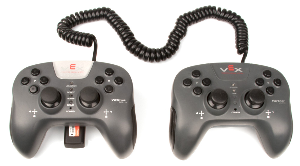
- Two Joystick Operation: If desired, a second Joystick can be added to allow two drivers to operate a single robot. Simply connect a second VEXnet Joystick or a Partner Joystick to your main VEXnet Joystick using a coiled handset cable plugged into the Joysticks’ PARTNER Ports. Only the main Joystick should have a VEXnet Key installed. When using the Default Code, you will need to install a jumper into Digital Port 11 in order to activate two-Joystick operation.
- Limit Switch Inputs: The Default Code allows jumpers or switches to be installed in the Analog Ports to limit certain motor directions. These are useful for stopping a motor when an arm bottoms out. A limit switch plugged in to Analog 1 will stop Motor 6 from turning counterclockwise when activated. A limit switch plugged in to Analog 2 will stop Motor 6 from turning clockwise when activated.
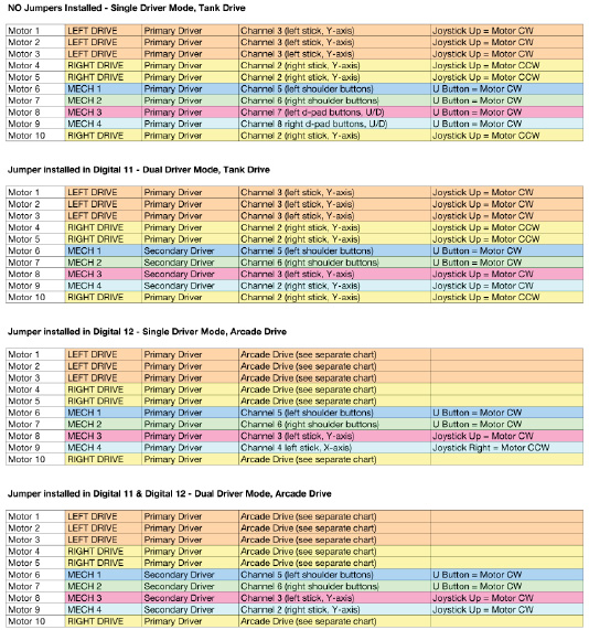
4. Default Operation:
Refer to the attached figures for details and options of Joystick input to Motor response. These motor directions will make a robot go forward when the joysticks are pushed up. Note the Jumper variations for each section.
Please note: The default code for the Cortex microcontroller varies from that of the PIC microcontroller. Please review and follow the tables in this document to ensure your robot behaves in the manner you wish.
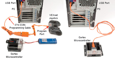
- The Cortex may be reprogrammed with user-created code. The hardware setup for wireless downloading is shown below. For non-wireless downloading, the VEXnet keys may be substituted with a USB A-A cable. You can also download code directly to the Cortex using the USB A-A cable.
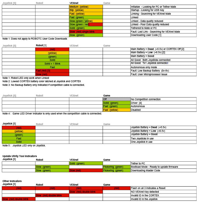
5. Diagnostics Information:
Refer to the following chart for Joystick and Cortex LED patterns and meanings.
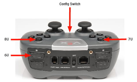
6. VEXnet Joystick Calibration Procedure:
- The Joystick must be linked to the Cortex Microcontroller using the VEXnet Keys.
- Hold the “6U” Back Switch depressed.
- While the “6U” Back Switch is depressed, use a small Allen Wrench (1/16” or smaller) or similar small straight tool to depress and hold the CONFIG Switch.
- Hold both Switches depressed until you see the Joystick LED Flash red and green – you can now release both Switches.
- There is a 10 second time limit to complete the following two steps.
- Move both Analog Joysticks to the maximum position desired in all 4 directions – Up, Back, Left, and Right.
- If a movement is not detected in all 4 directions, a timeout will occur after about 10 seconds and the Calibration Mode will be discontinued and the VEXnet LED will briefly flash red.
- The Joystick LED will continue to flash red and green during the calibration process.
- After movement is detected in all 4 directions, the Joystick LED will be ON and solid green.
- To save the calibration, depress and release the “8U” top button.
- If the calibration is accepted and saved, the Joystick LED will start flashing fast green for a few seconds.
- If the calibration is not saved, a timeout will occur after about 10 seconds and the Calibration Mode will be discontinued and the VEXnet LED will briefly flash red.
- To cancel the calibration, depress and release the “7U” top button. The Calibration Mode will be discontinued and the VEXnet LED will briefly flash red.
- If the Calibration Mode is discontinued or saved, the Joystick LEDs will resume their normal function after the VEXnet LED briefly flashes.
- If Joystick Master Firmware is downloaded into the Joystick, the Joystick will need to be recalibrated.
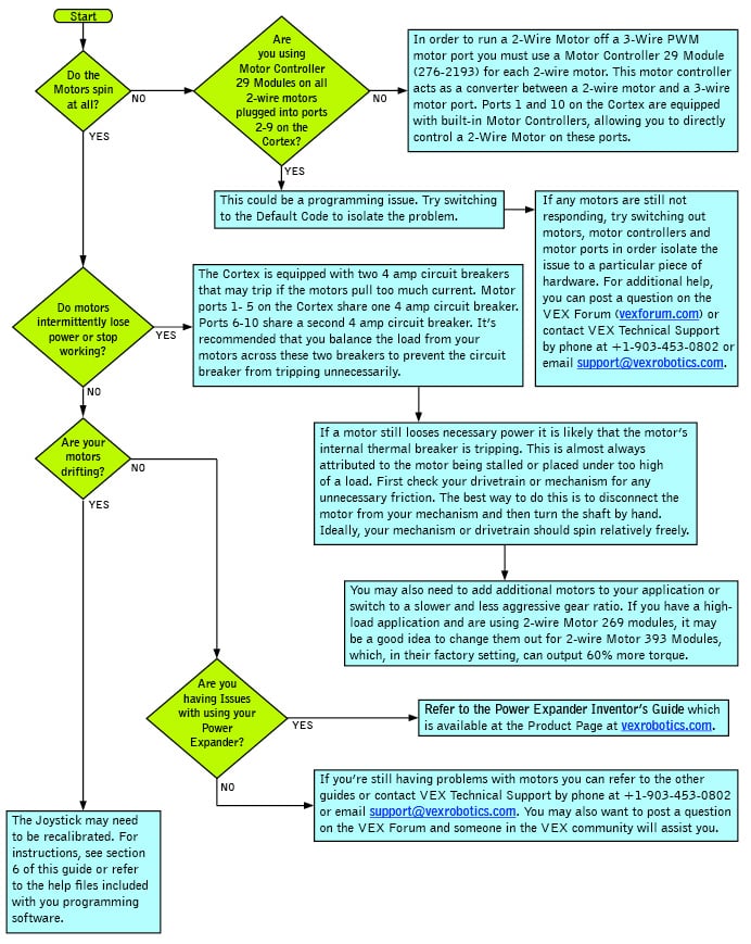
7. General Robot Troubleshooting Flowchart:

8. VEXnet Troubleshooting Flowchart
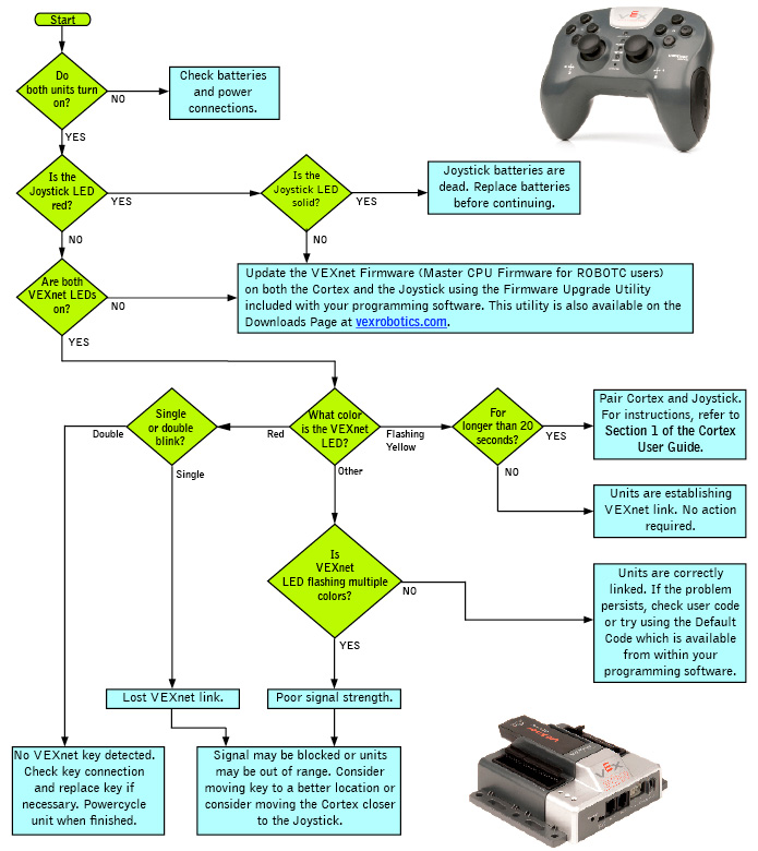
If the issue is still present after following this guide, update both the Cortex and Joystick with the most recent version of the VEXnet Firmware (Master CPU Firmware for ROBOTC users). If this does not resolve the problem, try using a different set of VEXnet keys. If you need further assistance you can post a question on the VEX Forum (vexforum.com) or contact VEX Technical Support by phone at +1-903-453-0802 or email [email protected].
9. Motor Troubleshooting Flowchart
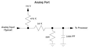
10. Analog Information:
Analog lines are input only and read about 0.2 volts when open. Circuit details are as follows:
- Analog input range is 0 to +5 volts.
- Analog to digital resolution is 12-bit, compiler resolution may vary.
- Analog circuit has a 470k pull-up to +5 volts, a series 10k resistor and a 20k resistor to ground.
- Analog inputs also have a 1000 pF capacitor to ground on the processor side of the 10k resistor.
- 3 dB bandwidth: 16 kHz.
Circuit connections as shown.
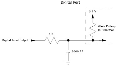
11. Digital Information:
When configured as an input, digital lines have a weak pull-up. When configured as an output, digital lines drive 0 volts for a low and 3.3 volts for a high. Circuit details are as follows:
- Digital input range is 0 to +5 volts.
- Digital drive is primarily limited by the 1k series resistor, so it can output a 2v high into 2k-ohms to ground or a 0.8v low into 7k-ohms to 3.3v.
- Digital inputs also have a 1000 pF capacitor to ground on the processor side of the 1k resistor.
- 3 dB input bandwidth: 150 kHz.
- Circuit connections as shown.
12. Circuit details of the Digital-to-Analog Port, SP:
- Circuit SP is connected to the Digital-to-Analog-Converter (DAC) output of the User Processor.
- Factory default Hex file does not support the DAC output. Check your compiler for availability and use.
- SP is an Analog Output when configured by compiler. Drive is primarily limited by a 5 kilo-ohm internal processor resistance and by the 100 ohm series resistor. Output swing of the processor into an open load is 0.2v to 3.1v, typical.
13. 2-Wire Motor Port outputs:
- Motor Port 1 and Motor Port 10.
- Maximum motor stall current: 3.0 amps at 8.5 volts.
- Motor chop rate: determined by the compiler. Default code chop rate: 1 kHz.
- Overcurrent protection: Motor Port 1 through Motor Port 5 shares one 4 amp circuit breaker. Motor Port 6 through Motor Port 10 shares a second 4 amp circuit breaker.
14. 3-Wire Motor Port outputs:
- Motor Ports 2 through 9.
- Maximum motor stall current: internally limited by motor assembly.
- Motor PWM output: determined by the compiler. Default is 1 to 2 milliseconds high time and a 17 millisecond period.
- Overcurrent protection: Motor Port 1 through Motor Port 5 shares one 4 amp circuit breaker. Motor Port 6 through Motor Port 10 shares a second 4 amp circuit breaker.
15. UART Connections:
- Ground, Power (+5v), RX data in, TX data out. Data rate, byte width, (transmit) stop bits, parity, etc. are determined by the compiler.
- Default for LCD data: 19,200 baud, 8 data bits, 1 stop bit, no parity and no flow control.
16. I2C Connections:
- Ground, Power (+5v), Clock, Data. Data rate, byte width, (transmit) stop bits, parity, etc. are determined by the compiler.
- The factory default Hex file does not support I2C.
17. Notes:
- Do not use a USB Hub with the Cortex or Joystick. Always make a connection directly to a PC USB port when needed. USB Hub performance is not supported.