The most frequently used lifting mechanism in competition robotics is a rotating joint.
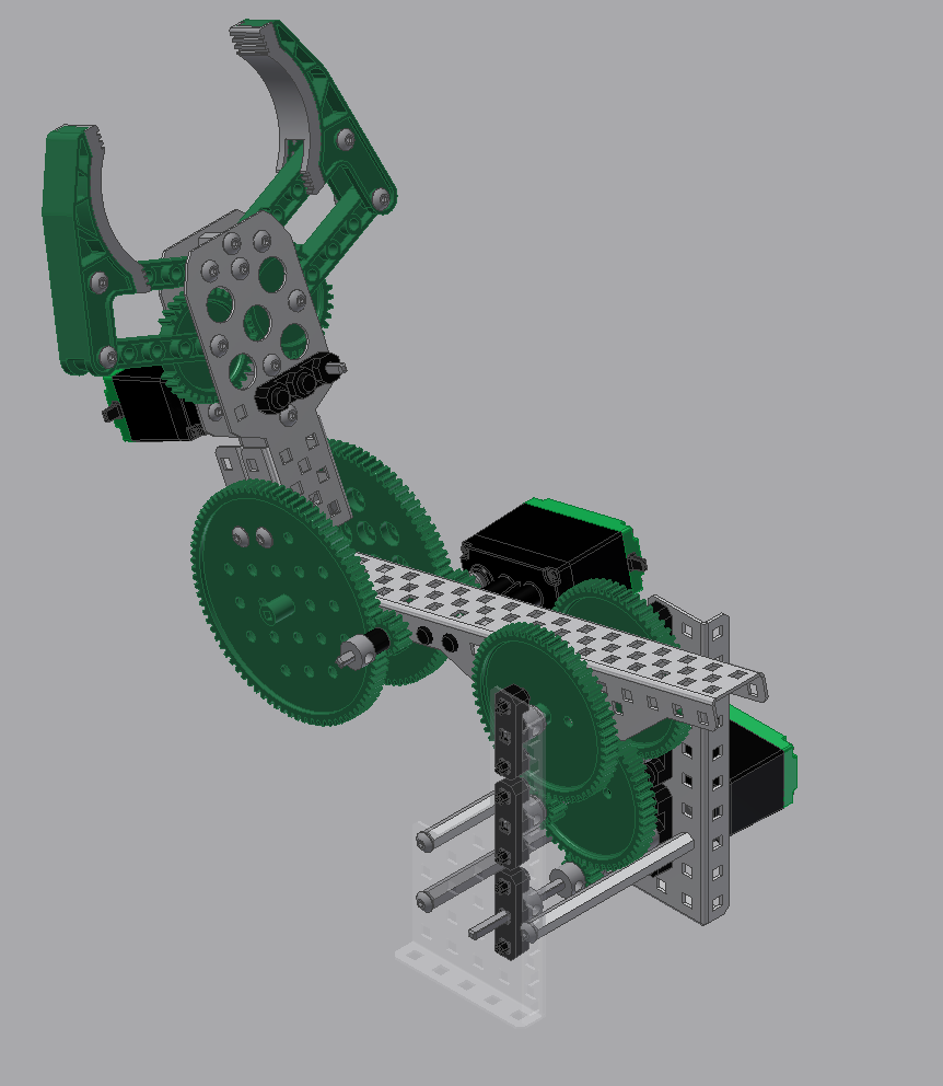
The above example shows a 2-jointed arm, which includes a shoulder joint and a wrist joint (note that joints on a robot arm are often named similarly to a human arm). These joints are constructed by locking part of the robot structure onto part of a motion system. In the above case, the shoulder joint includes an arm locked to the gears of the shoulder gearbox – as these gears turn, the arm turns as well. Similarly, the claw is locked to the gears of the gearbox attached to the end of the arm.
One might notice in the above example that the shoulder joint has a much higher gear reduction than the wrist joint. This is done because of motor loading. The shoulder joint needs to lift the weight of the arm, the weight of the wrist joint, the weight of the claw, and whatever object the claw has picked up. The wrist joint only needs to lift the weight of the claw and the object it has grabbed. The shoulder joint also needs to lift this weight with a much longer lever arm than the wrist joint, so it is under significantly more torque. Each joint is designed to handle the loads which will be applied to it. These concepts were discussed in Unit 7 and Unit 8.
An example of a double reduction rotation joint is seen below.
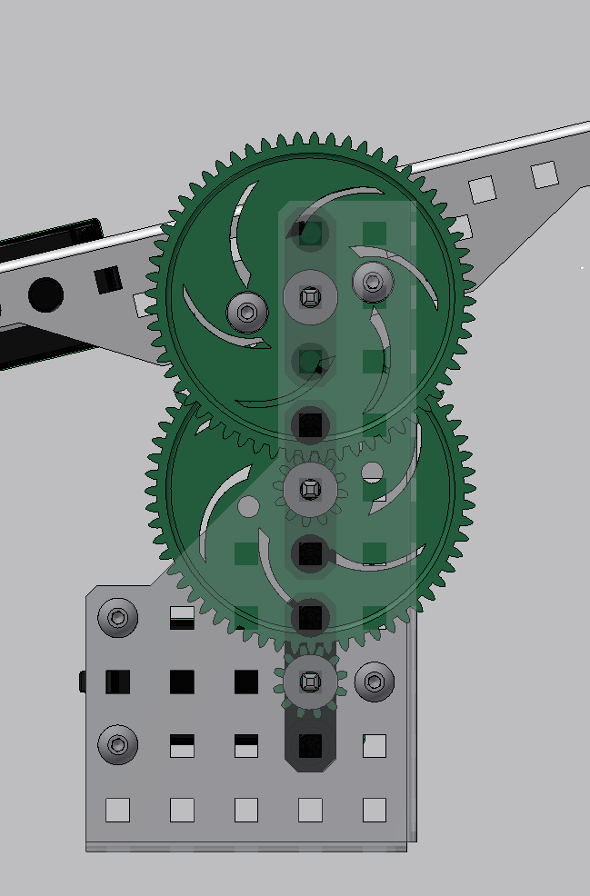
This joint has two stages of 12:60 gear reductions. The second stage is attached directly attached to the robot arm. The second stage also has two of the same gear reduction running in parallel; this means that the load is divided evenly over these two sets of gears. By reducing the load on individual components, the joint is less likely to have a failure (broken gear, etc).
A SHOCK LOAD is an instantaneous spike of loading on a mechanical system. Imagine someone grabs onto the arm of a robot and pushes down on it as hard as they can in a jerking motion. This would apply a shock load to the arm gearbox. It is always a good idea to design robot joints robustly enough to withstand these shock loads. Running multiple parallel gear reductions will spread shock loads and prevent damage.
The first stage of gear reduction does NOT utilize parallel reductions; it has only one set of meshing gears. This is because the impact of a shock-load is lowest at the part of the gearbox closest to the motor. Typically gear stages closest to the motor do not need to be as robust as stages further into the gearbox.
Joint Loading:
In order to effectively utilize a motor, one needs to adjust the load applied to its motor such that it runs within acceptable parameters. Methods for using mechanical advantage and gear reduction to optimize motor loading were discussed in Unit 7 and Unit 8.
If there is some force applied at the end of the robot arm (as discussed in Unit 7) it will apply a torque on the joint equal to the magnitude of the force multiplied by its distance from the joint. This applied force is partially caused by the weight of the arm itself, as well as any forces the arm will encounter during operation (weight of objects it is lifting, etc.)
When choosing the appropriate gear reduction for an arm, it is a good idea to add a Factor of Safety to these forces to ensure the joint can handle any unanticipated loads it encounters. A factor of safety, also known as a margin of safety, describes the amount of overage the system can handle. Basically if the robot needs to be able to lift with a force of 10 N, one might design the robot to handle 12 N. This would be a factor of safety of 1.2 (10 * 1.2 = 12). This factor of safety will take care of any unexpected loads the arm encounters. It is always a good practice to take the unexpected into account when designing.
Joint Speed:
Often it is important for a joint to move as quickly as possible; however, this is not always practical. Designing a joint to be too fast may make it uncontrollable without advanced software.
There are two approaches to choosing the gear reduction required for a rotating joint. Either method will work for any rotating joint design. If the amount of load the joint can lift is critical, designers should use Approach 1. If the speed of the joint is more important than what will be lifted, designers should use Approach 2.
Approach 1 – Start with Loading:
Step 1 – Determine the applied load on the end of the arm, and the length of the arm.
Step 2 – Determine the maximum load which can be applied on the motor. (Refer to Unit 7).
Step 3 – Determine the required gear reduction which results in the desired motor loading.
Step 4 – Calculate how fast the arm will be rotating with this gear reduction.
Step 5 – Determine if this is a “good” speed.
Step 6a – If it is “good”, build it.
Step 6b – If it is too fast, determine how fast the joint needs to move, and then calculate the gearing required for this speed (it will be slower than the previously calculated speed). Then build it.
Step 6c – If it is too slow, add additional power to the system so it can handle this load at a faster speed (add additional motors to this joint). Then recalculate.
Step 6d – If the end result does not meet expectations, the constraints of the system need to be reevaluated and a redesign should be considered.
Approach 2 – Start with Speed:
Step 1 - Determine the desired speed of the joint, i.e. 90 degrees per second.
Step 2 – Determine the required gear reduction to achieve this desired speed. (Refer to Unit 8).
Step 3 – Determine the maximum load which can be applied on the motor. (Refer to Unit 7).
Step 4 – Determine the maximum load which can be lifted by the arm based on the gear reduction from step 2 and the maximum motor load from step 3.
Step 5 – Determine if this maximum lifting load is acceptable based on what the load on the joint will likely be (including safety factor).
Step 6a – If the load is “good”, build it.
Step 6b – If the load is too low, and the designer is willing to reduce the speed of the joint to accommodate this load, he or she should redesign based on Approach 1, above.
Step 6c – If the load is too low, and the designer is NOT willing to reduce the speed of the joint, he or she should add additional power to the joint and then recalculate.
Also note: reducing the length of the arm attached to the joint will reduce the amount of load on the motor (as discussed in Unit 7). This is one of the options a designer can choose if the output result does not meet his or her expectations.
Both of the above approaches will work well for designing a rotating joint. Each process requires iteration to be successful, and designers may find themselves doing and redoing calculations in an effort to find a design which works best for their given situation.