Based on the lessons learned in Unit 7, adjustments to mechanical advantage are important to the design of DC motor systems. DC motors sometimes have current limits they must stay under or other load limits. Designs sometimes require certain speeds, which motors must be geared up or down to achieve.
The first step in these types of design problems is to calculate the load the motor must be under to meet the design criteria. This is done using the motor characteristics, the design criteria, and the formulas and lessons used in Unit 7. After this, it is a matter of taking the output requirements and the input limits and calculating the ratio required.
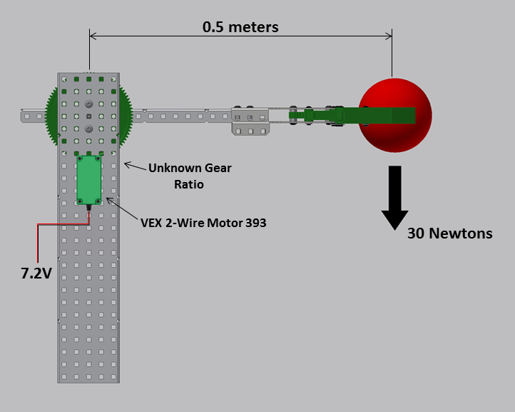

For the above arm configuration, assume the system has one VEX 2-wire Motor 393, and that this motor cannot draw more than 2.5 amps at any time. What gear ratio is needed to lift the 30 Newton object and not exceed this current draw?
The first step is to calculate the torque applied by the arm:
Torque = Force x Distance = 30 N x 0.5 m = 15 N-m
The next step is to calculate the torque load which will cause the motor to exceed 2.5 amps:
Torque Load = (Given Motor Current – Free Current) x Stall Torque / (Stall Current – Free Current)
Torque Load = (2.5 amps – 0.37 amps) x 1.67 N-m / (4.8 amps – 0.37 amps)
Torque Load = (2.13 amps) x 1.67 N-m / (4.43 amps)
Torque Load = 0.803 N-m
So if the torque load at the output of the gearbox is 15 N-m, and the load on motor can’t be more than 0.803 N-m, what gear reduction is required?
Output Torque = Input Torque x Gear Reduction
Re arranging:
Gear Reduction = Output Torque / Input Torque
Gear Reduction = 15 N-m / 0.803 N-m = 18.68
Based on this example the gear reduction required is 18.68. However, as discussed above it is not always possible to achieve specific gear ratios with the gears on hand. Assuming the designer only has 12-tooth, 36-tooth, 60-tooth, and 84-tooth gears, calculate a compound reduction that creates the overall gear ratio required for the above example.
There are many different solutions possible; the most important thing is that the compound ratio chosen results in a reduction of more than 18.68 to achieve the design goals shown above.
Considerations: Designers should try to achieve the required reduction in as few stages as possible, and should try to get as close to 18.68 as possible without going under.
HINT: One can look at the big list of reduction options shown previously in this unit, and see which ones multiplied together as a compound reduction come close to 18.68.
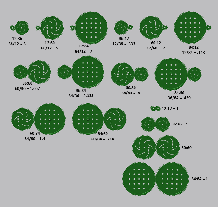
How about 12:60, then 12:60?
60 / 12 = 5
60 / 12 = 5
5 x 5 = 25
25 is greater than 18.68, so it is acceptable – however, 25 is a lot more reduction than required, so the arm will move slower than is necessary to achieve the design goal. Is there another option which is closer to 18.68?
How about 12:36, then 12:84, as a simple 2-stage compound gear reduction?
36 / 12 = 3
84 / 12 = 7
3 x 7 = 21
21 is greater than 18.68, so 12:36 then 12:84 is an acceptable choice, this option is much closer to the minimum required reduction than 12:60, 12:60!