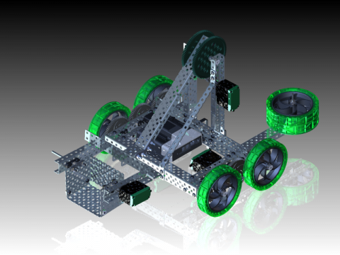
You have built a virtual model of the ClawBot in Autodesk Inventor, but based on the new game requirements, you have to design a replacement object manipulator. The claw does not pick up the game object as effectively as you want, so you are going to design a new scoop manipulator in Autodesk Inventor.
In this project, there are 11 videos, including the Overview and Summary. To use the videos, click the link and review the content. Pause, rewind, fast forward, and stop features are available as the student reviews the content. The workflow in these videos includes
- Assembling the scoop frame using simple pick and place techniques.
- Designing a new scoop bucket using existing parts.
- Assembling the scoop bucket onto the frame and arm.
- Creating a drive train and motor assembly.
- Using Inventor Studio to create rendered images and an animation of your robot design.
Overview
Click here to download and view this video offline.
In this video, all the key phases of designing a scoop manipulator in Autodesk Inventor software will be reviewed.
Video 1:Create the Base Frame
Click here to download and view this video offline.
In this video, students will design and model the base frame. Using the supplied custom parts, the base frame of the scoop manipulator is assembled. The structural frame members have square holes that have to be aligned correctly. Assembling the parts using the iMates attached to each hole simplifies the process by reducing the number of clicks required.
Note - The files required for this activity must be downloaded. Please select the data set which matches the version of Autodesk Inventor will be used for this activity. Unzip these files and save them a new project folder called Manipulator.
Video 2:Create the Shaft Assembly
Click here to download and view this video offline.
In this video, students will model the shaft assembly on the base frame. They assemble a bearing flat, bearing pop rivets, a shaft, and a shaft collar on the base frame to create a shaft assembly.
Video 3:Design and Model the Scoop
Click here to download and view this video offline.
In this video, students will design a new manipulator using custom parts. To model the new scoop bucket design, a series of custom parts are supplied. These parts are placed in a separate file. The parts are constrained and the separate file can then be placed as a subassembly in a frame assembly file.
Video 4:Assemble the Scoop and Frame
Click here to download and view this video offline.
In this video, students will constrain the scoop to the base frame. The scoop subassembly is placed in the base frame assembly. Work planes are used to center the scoop in the frame and one of the holes is aligned to the shaft. A check is made to ensure that all the parts are moving correctly.
Video 5:Place a Lock Bar on the Shaft Assembly
Click here to download and view this video offline.
In this video, students will control the motion of the shaft and scoop using a lock bar. To lock the scoop to the shaft, a lock bar is placed on the shaft and bolted to the scoop. The scoop will now spin with the shaft.
Video 6:Assemble the Scoop to the Robot
Click here to download and view this video offline.
In this video, students will place the scoop subassembly in the main robot assembly. With the scoop bucket completed, the subassembly is placed in the main robot assembly and constrained to the arm.
Video 7: Add a Counterweight to Complete the Design
Click here to download and view this video offline.
In this video, students will resolve a design issue by adding a counterweight. Analyzing therobot design using the Center of Gravity tool has shown that the scoop bucket may topple the robot. To resolve this problem, a counterweight is designed and added to the rear of the robot frame.
Video 8:Review the Animation Setup
Click here to download and view this video offline.
In this video, students will add and review constraints that will be used to animate the robot. Before you create an animation, it is important to check the existing constraints and add new constraints if required.
Video 9:Animate the Robot
Click here to download and view this video offline.
In this video, students will create an animation of the robot. In Inventor Studio, an animation is created. The robot moves to a wall where it collects the game object, moves away from the wall, and at the same time, the scoop swivels and the arm is raised.
Summary
Click here to download and view this video offline.
In this video, students will review the workflow required to design and model the scoop manipulator. Designing and modeling the scoop requires the following workflows in Autodesk Inventor:
- Assembling parts using iMates.
- Adding standard parts.
- Creating a subassembly of the scoop.
- Assembling the scoop bucket to the main robot.
- Using Inventor Studio to create an animation.
Want to try more projects based on VEX robots and other exciting challenges? Click the link to access the Autodesk Digital Steam Workshop.

