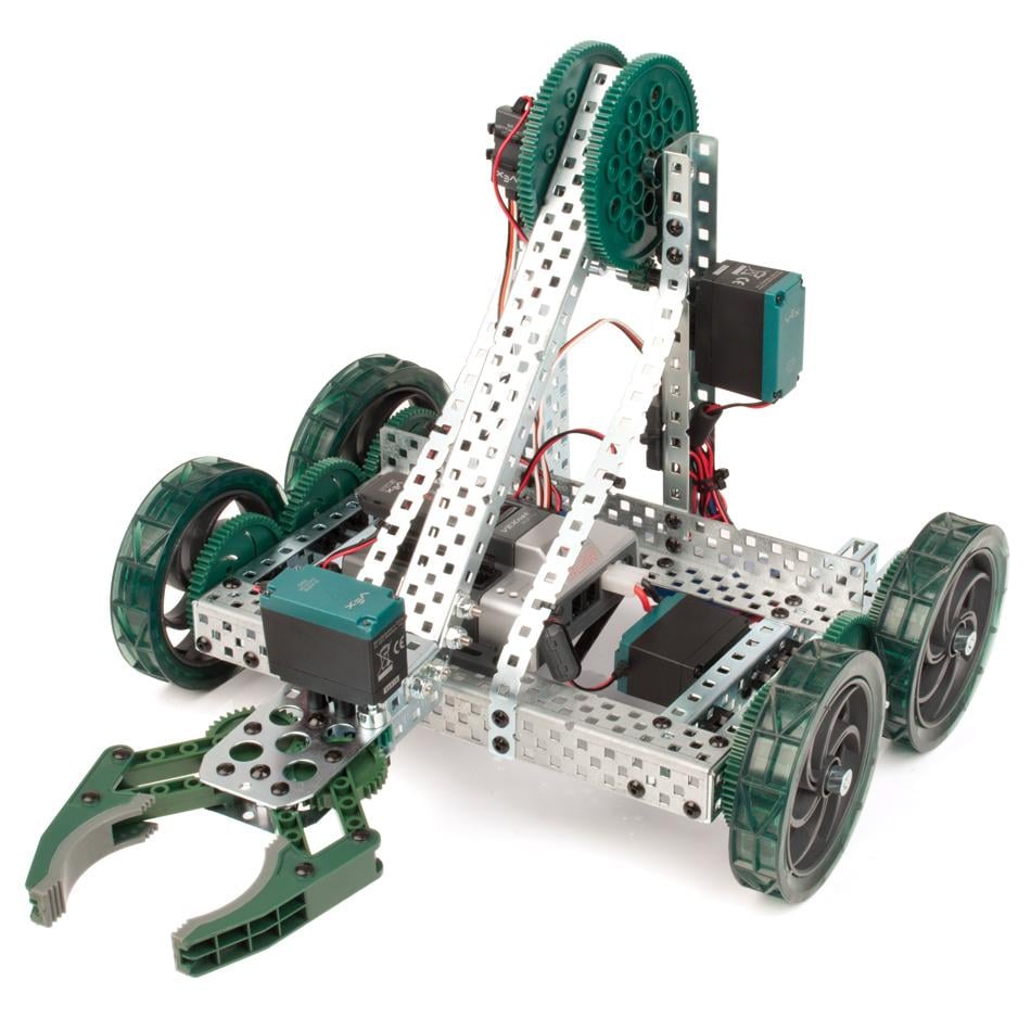
In Unit 2, the mechanical construction of the VEX Clawbot was completed. The next steps are to hook up the VEX Cortex Microcontroller and VEXnet Joystick to get the robot fully operational.
Plugging In and Controlling Motors
The VEX Clawbot has four motors which power the two sides of the drivetrain, claw motor and arm motor. How does the VEXnet Joystick send commands to these specific motors? Earlier in this unit, the 802.11 VEXnet wireless link was discussed, which allows users to send commands to microcontroller. There was also discussion of the preloaded default code, loaded onto the microcontroller, which allows users to quickly get their robots running. This default code is programmed to map the controls on the VEXnet Joystick, directly to the motor ports on the Cortex Microcontroller. When the following motors are plugged into the following ports, the default code allows for the following controls.
|
Motor |
Motor Port |
VEXnet Joystick Control |
|
Left Drive Motor |
1 |
Left Joystick |
|
Claw Motor |
6 |
Left Shoulder Buttons |
|
Arm Motor |
7 |
Right Shoulder Buttons |
|
Right Drive Motor |
10 |
Right Joystick |
Plug the left drive motor directly into motor port 1 on the Cortex Microcontroller. Make sure the red wire is on the left side.
- Plug the right drive motor directly into motor port 10 on the Cortex Microcontroller. Make sure the red wire is on the left side.
- Plug the claw motor into a motor controller 29, making sure that the colors of the wires match up. Plug the other end of the motor controller 29 into the Cortex Microcontroller. This is a keyed connection, so there is only one way to plug this wire in.
- Plug the arm motor into a motor controller 29, making sure that the colors of the wires match up. Plug the other end of the motor controller 29 into the Cortex Microcontroller. This is a keyed connection, so there is only one way to plug this wire in.
- For more details on wiring the VEX Clawbot see page 16 of the Clawbot Assembly Instructions.
Installing Batteries and VEXnet Keys
- Plug a 7.2v VEX battery into the 7.2v battery port on the front of the Cortex Microcontroller, next to the on/off switch. This is a keyed connection, so there is only one way to plug this wire in.
- Plug a VEXnet 802.11g key to the Cortex Microcontroller into the USB slot on the top of the Cortex Microcontroller.
- Using a Phillips head screw driver or VEX 3/32 Allen Wrench (depending on which version of the Joystick is used), remove the screws that attach the battery cover to the VEXnet Joystick. Remove the battery cover.
- Install six (6) identical AAA batteries into the VEXnet Joystick. DO NOT mix different types of batteries.
- Reinstall the battery cover by inserting the two tabs of the battery cover along the back edge to aid in installation, and then reattach the screws that were removed earlier.
- Plug a VEXnet 802.11g key to the VEXnet Joystick into the USB slot above the battery cover.
Getting Started
- Now that the Robot is completely wired and ready to go, it’s time to take it for a test drive! The above chart explains the control configuration for the Clawbot. The Clawbot by default is set to operate in “Tank Drive” mode. This means the left and right wheels are controlled separately by individual joysticks; this is the same way a tank is controlled. To make the robot go forward, push up on both joysticks. To make the robot go backwards, push down on both joysticks. To make the robot turn left, push the right stick up and the left stick down. To make the robot turn right, push the left stick up and the right stick down. Experiment with different combinations to achieve various “arc” patterns while driving.