The gear train represents the part of the drivetrain that transmits power from the motor, to the wheel.
Wheel Speed:
The first concept to understand is how to figure out how fast the robot moves across the field based on how fast the wheel is spinning. For each time the wheel makes a full rotation, it will roll forward a distance equal to its circumference. So if one calculates the circumference of the wheel, one knows how far the robot goes per wheel revolution.

The circumference of a wheel is equal to its diameter multiplied by Pi (a mathematical constant which is about 3.14).
Once one knows the circumference of the wheel, it is possible to calculate how fast the robot is travelling based on the wheel’s rotational speed. In the example above, the wheel diameter is 101.6 mm [4 inches] and is spinning at 100 RPM (revolutions per minute). So based on this, how fast is the robot travelling (in mm/second)?
Circumference = Diameter x Pi
Circumference = 101.6 mm x 3.14
Circumference = 319.024 mm
So the robot moves 319.024 mm per 1 wheel revolution. The wheel is moving at 100 revolutions per minute, or 100 revolutions per 60 seconds.
From this, one can calculate the linear ground speed of the robot:
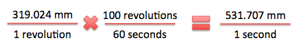
So the robot is moving at about 532 mm/second or 0.532 meters/second.
Armed with this method, and knowing the specifications for VEX motors, one can determine the necessary gear ratio for a VEX robot to hit a desired top speed.
EXAMPLE – Calculating Gear Reduction to hit a Desired Top Speed:
One can consider the case of a robot that has a wheel with a diameter of 69.85mm (2.75 inches) and a motor that has a free speed of 100 RPM. In this case, if the designer wants the robot to have a desired free speed of 900 mm / s, what gear reduction is required? (One needs to use the knowledge of Gear Ratios discussed in Unit 8).
The first step in calculating this is to determine what RPM the wheel is required to spin at to achieve the desired top speed of 900 mm / s.
Circumference = Diameter x Pi
Circumference = 69.85 mm x 3.14
Circumference = 219.329 mm
So the robot moves 219.329 mm per 1 wheel revolution. Converting the goal speed into RPM based on this circumference results in the following:
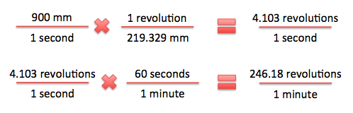
If the wheel needs to spin at 246.18 RPM, and the motor spins at 100 RPM one can calculate the required gear reduction using an equation from Unit 8:
Gear Reduction Required = Input Speed / Output Speed
Gear Reduction Required = 100 RPM / 246.18 RPM
Gear Reduction Required = 0.4062
So the designer needs to use a gear reduction of 0.4062 or less to achieve a top speed of greater than 900 mm / s.
Motor Loading & Gearing:
The second concept designers must consider when designing drivetrains is how motor-loading affects gear train design. In particular, it is important to consider the maximum load applied to the motor by the drivetrain. This occurs during a situation where a robot is pushing against a stationary (immovable) object, and is running full throttle into it. In this situation the wheels should slip on the floor, and the friction between the wheels and the floor will act as a brake on the motor.
The first step is determining how many wheels are acting as a brake on the gearbox. Only wheels directly linked through gearing or chain will apply load to the gearbox and motor.
The second thing to consider is to determine how much of the robot’s weight is resting on each of those wheels. As discussed earlier, the traction between the wheels and the floor is dependent on the normal force pressing them together.
As an example, one could consider the robot below:
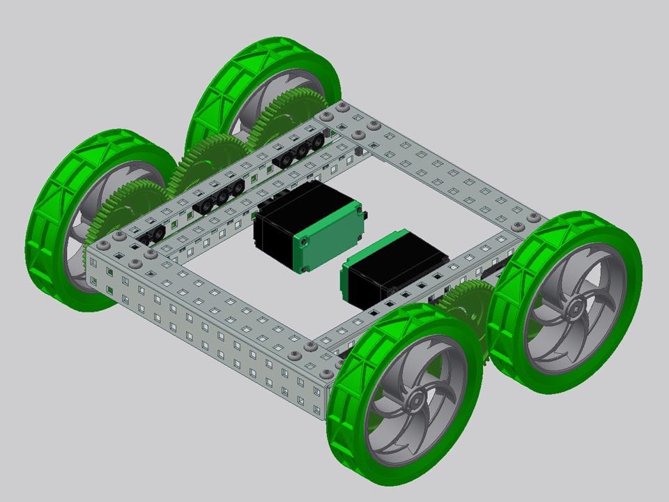
In this case, the robot’s weight is evenly divided among the 4 robot wheels, and each motor is directly linked through gearing to two of the wheels (right vs. left). This means that each motor has 1/2 the robot’s traction acting on it as a brake.

As shown in the above image, the friction of each wheel creates a torque which opposes the motion of the motor. Both of the torques contribute load on the motor.
If the gear train has multiple motors associated with it (i.e. two motors driving one geared set of wheels), then the torque will be divided evenly between them.
It is important to design the gearing such that the load applied on each motor is not higher than the motor limit (as described in Unit 8.) Designers should use the principles of gear reduction to ensure that the motor limit is not exceeded; when in doubt, gear the robot slower for less loading.
Using the two concepts discussed above, along with those from Unit 7 and Unit 8, designers should be able to gear a robot so it moves at a desired speed. They should also ensure there is no excessive load on the motors.