Actuators are mechanisms used to act upon an environment, usually for moving or controlling a mechanism or system. Actuators drive everything that moves on a competition robot. The most common type of actuator in this application is a motor; in particular, VEX Robots utilize Direct Current (DC) Motors.
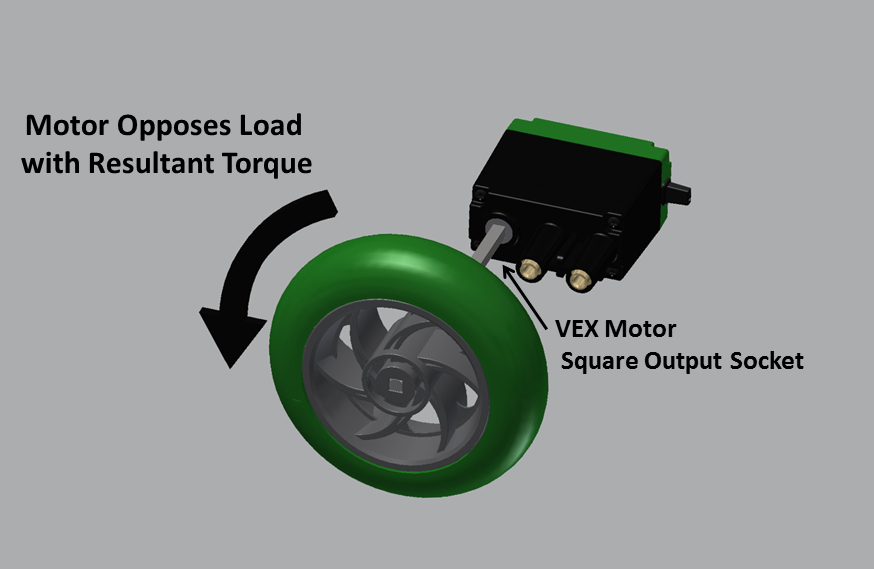
Motors convert electrical energy into mechanical energy through the use of electro-magnetic fields, and rotating wire coils. When a voltage is applied to a motor it outputs a fixed amount of mechanical power. The mechanical power is seen as the motor’s output (usually some shaft, socket, or gear), spinning at some speed with some amount of torque.
Motor Loading
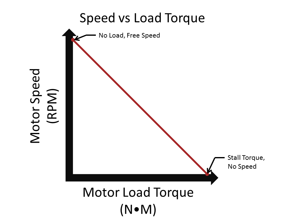
Motors only apply torque in response to loading. Ideally, with no loading on the output the motor will spin very, very fast with no torque. This never happens in real life, since there is always friction in the motor system acting as a load and requiring the motor to output torque to overcome it. The higher the load placed on the motor output, the more the motor will “fight back” with an opposing torque. However, since the motor outputs a fixed amount of power, the more torque the motor outputs, the slower its rotational speed. The more work one makes the motor do, the slower it spins. If one keeps increasing the load on the motor, eventually the load overcomes the motor and it stops spinning. This is called a STALL.
Current Draw
The motor draws a certain amount of electrical current (expressed in units of amps) depending on how much load is placed on it. As the load increases on the motor, the more torque the motor outputs to overcome it and the more current the motor draws.


As seen in the graphs above, current and torque load are proportional. More torque load means more current draw, but current and rotational speed are inverse. The faster the motor spins, the less current it draws.
The “key” Motor Characteristics
All motors are different, and their properties vary depending on their type, configuration, and manufacture. There are four main characteristics that govern the types of DC motors used commonly in competition robotics.
Stall Torque (N-m) – The amount of load placed on a motor that will cause it to stop moving.
Free Speed (RPM) – The maximum rotational speed a motor will run at when it is under no load.
Stall Current (Amp) – the amount of current a motor will draw when it is stalled.
Free Current (Amp) – The amount of current a motor will draw when it is under no load.

Based on the above relationships, one can see how the concept of power comes into play. With a given loading, the motor can only spin at a certain speed.
Since the relationships shown above are linear and proportional, it is a simple matter of plotting the torque-speed and torque-current graphs for any motor by experimentally determining two points on each graph.
Varying Power with Voltage
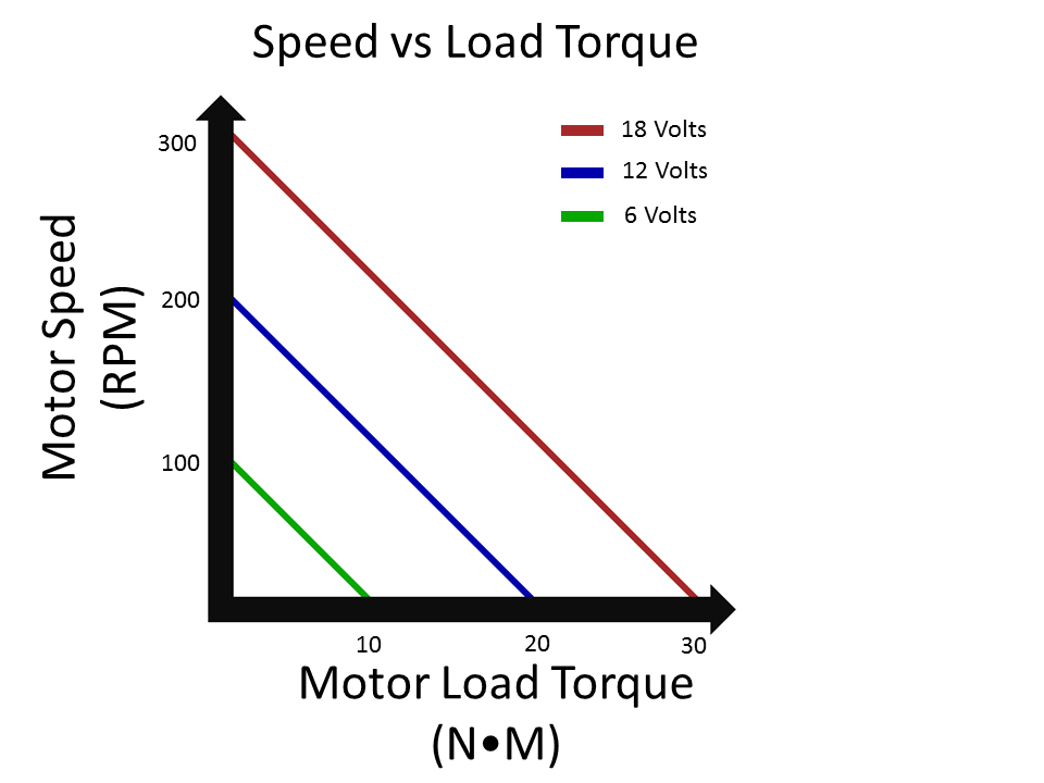
The Power output of a DC Motor varies with the voltage applied. This means that the more voltage is applied, the more power is available and the faster the motor can do work.
If a motor is under a fixed amount of load, and the voltage is increased (resulting in an increase of power), what will it do? It will spin faster! There is more power available to accomplish the same amount of work.
This means that the above motor characteristics change depending on the Voltage applied to the motor, and as such they need to be listed at a given Voltage (i.e. “Tested at 12V”.) In fact, the four characteristics above vary proportionally with applied voltage. For example, if one knows a motor has a free speed of 50 RPM at 6V, if the voltage is doubled to 12V the free speed doubles also, and can be calculated to be 100 RPM.
One can calculate the value of one of these characteristics at a specific voltage if one knows the characteristic at another voltage by multiplying the known value by the ratio between the voltages. Note, this does not apply to the motor's Free Current, which is the same at any voltage.
New Value = Spec Value x (New Voltage / Spec Voltage)
For instance, in the example described above a motor’s free speed is specified at 50 RPM at 6V. The designer is planning to run the motor at 8V – what will be the free speed at this voltage?
Free Speed @ 8V = Free Speed @ 6V x (8V / 6V) = 50RPM x (8/6) = 66.66 RPM
So what implications does varying voltage have for control? The motors on a robot aren’t just on / off devices. A robot designer can vary the voltage going to the motor under load to get different amounts of power, and varying speed. This is done using electrical devices known as motor controllers, which regulate the voltage supplied to the motors.
Motor Limits & Calculations
Does this mean a designer can keep adding voltage to a motor until it is capable of outputting the power needed for an application? Not quite, because motors have limits. At some point the power will be too much for the motor’s electrical windings to handle and it will fail (usually, with a puff of white smoke.) Luckily, this doesn’t happen with VEX motors – they all have internal thermal breakers that will cut the current being delivered to the motor if they get too hot. This is good because it means the motors won’t burn out, but it presents a new constraint for designers: making sure the motors don’t trip their breakers! How do designers do this? By designing their systems so that the motors don’t draw more current than a specified amount by limiting the amount of load that will be applied.

Arm Load Calculation
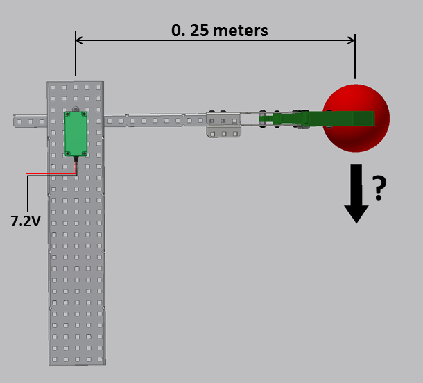
In the above example, a known motor at a known voltage is driving a known robot arm. In this scenario, what is the maximum weight the robot can hold stationary?
To solve this problem, a designer must understand that the maximum weight the robot can hold stationary occurs at the stall torque of the motor. If the motor is stalled, it is applying a torque of 1 N-m on the robot arm, which is 0.25 meters long. Torque = Force * Distance
Force = Torque / Distance = 1 Newton-meter / 0.25 meters = 4 Newtons
The arm can hold up 4 Newtons at motor stall. Any more and the arm will drop down.
Torque Load Calculated from Current Limit:
This is simple, but things get more complicated when one needs to consider a current limit. Say for instance in the above example a current limiting breaker is present in the motor that will trip if the motor draws more than 2 Amps. What is the maximum weight the robot can hold without tripping this breaker?
Now, the motor is not operating at stall torque – if the motor is at stall it will draw the stall current of 3 amps and trip the circuit breaker. The designer needs to figure out what torque load the motor must be under to maintain current draw less than 2 amps. How does one go about doing this?

Looking at the above graph and remembering that the relationships are linear, an equation can be derived to calculate the torque loading at any specified current draw.
The equation for a line is y = mx + b where y is the value in the y-axis, x is the value in the x-axis, m is the slope of the line, and b is where the line intersects the y-axis (y-intercept).
The slope of the line can be expressed as m = (Change in Y / Change in X) = (Stall Current – Free Current) / Stall Torque
The Y-Intercept is the free current.
The Y value is the current at a given point on the line and the X value is the torque loading at that point.
The equation can be expressed as:
Current = ((Stall Current – Free Current) / Stall Torque) x Torque Load + Free Current
Rearranging to solve for Torque Load:
Torque Load = (Current – Free Current) x Stall Torque / (Stall Current – Free Current)
Plugging the parameters of the above example in, one can solve for the torque load which results in a current draw of 2 Amps.
Torque Load = (2 Amps - .1 Amps) x 1 N-m / (3 Amps - .1 Amps)
Torque Load = (1.9 Amps) x 10 N-m / (2.9 Amps)
Torque Load = .655 N-m
Based on this calculation, the designer knows that if the torque applied to the motor is above 0.655 N-m, the motor will exceed 2 amps of current draw, and the breaker will trip. All that is left is to calculate how much force can be placed on the arm.
Force = Torque / Distance = 0.655 N-m / 0.25 m = 2.62 N
If the robot arm picks up an object heavier than 2.62 N, it will trip the motor circuit breaker.
Motor Speed from Torque Load Calculation
In the above example, how fast does the motor move when it is at the current limit? Based on the calculation in the previous step, the designer needs to determine the motor speed at a load of 0.655 N-m.
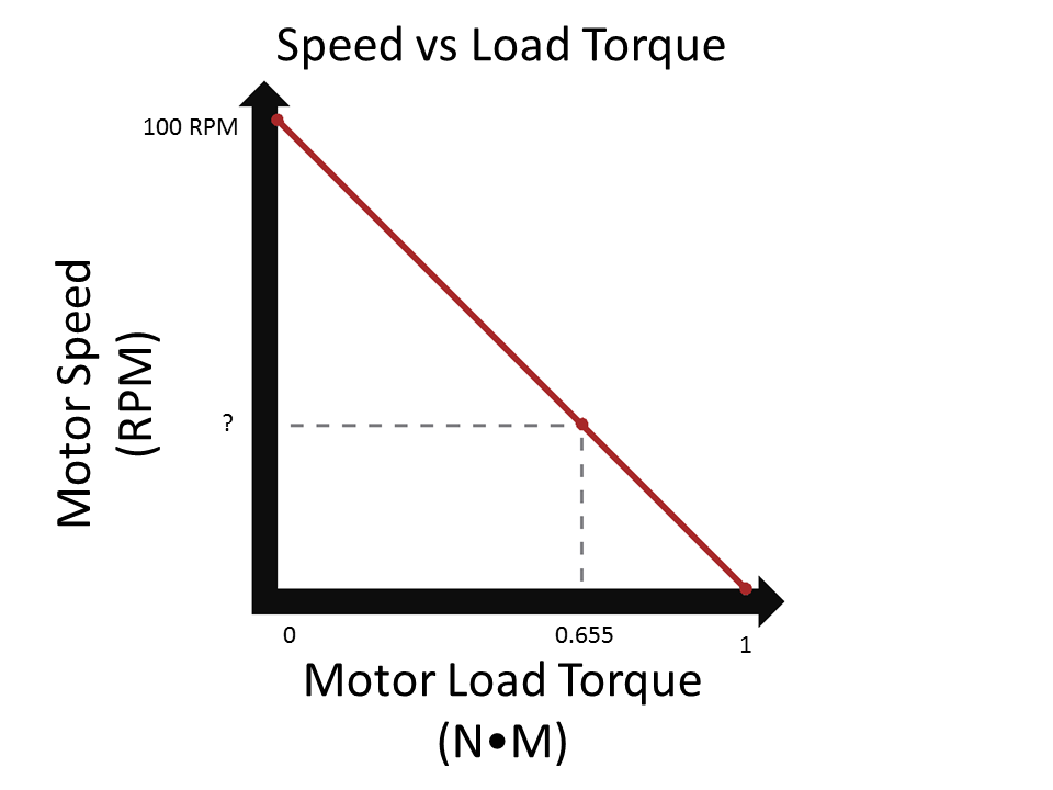
Looking at the above graph, it is possible to derive an equation to calculate the motor speed at any given torque load in a way similar to the current draw equation from the last example.
In this case, the slope of the line is expressed as m = (Change in Y) / (Change in X) = -(Free Speed) / (Stall Torque).
Note: the slope is negative.
The Y-Intercept is the Free Speed
The Y value is the speed at a given point on the line, and the X value is the load torque at that point.
The equation is expressed as:
Speed = -(Free Speed / Stall Torque) x Torque Load + Free Speed
Plugging the parameters of the above example in, one can solve for the speed of the motor at a torque load of 6.55 in-lbs:
Speed = -(100 RPM / 1 N-m) x0.655 N-m + 100 RPM
Speed = -(100 RPM/N-m) x 0.655 N-m + 100 RPM
Speed = -65.5 RPM + 100 RPM = 34.5 RPM
The motor will spin at 34.5 RPM when it is under a torque load of 0.655 N-m, while drawing 2 amps and lifting an object weighing 2.62 N.
Multiple Motors
When an application requires more power than a motor can handle, a designer has three options:
- Deal with it, and change the requirements of the problem so that lower power is acceptable.
- Switch to a more powerful motor.
- Use more than one motor in the application.
What happens when multiple motors are used on one application? Simple – they balance the torque load between them. If 2 N-m of torque is applied, each motor will have a torque load of 1 N-m, and react accordingly.
A simple way to think about it is that the motors take on the characteristics of one super-motor with combined specs of the individual motors. The stall torques, stall currents, and free currents add together but the free speed doesn’t change.

The above chart shows the specifications for the VEX 2-Wire Motor 393, and shows the specifications one would get when two are combined into the same application.
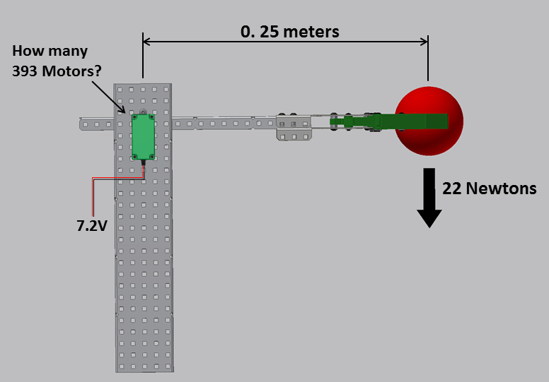
In the above example how many VEX 393 motors would it take to hold the object stationary?
The torque load on the motors can be calculated as follows:
Torque Load = Force x Distance = 22 N x 0.25 m = 5.5 N-m
Based on this torque load, one can compare it with the Stall Torque of the VEX 393 motor and determine how many would be needed.
5.5 N-m / 1.67 N-m = 3.29 motors
Thus, it would take 4 motors to hold up the arm in the example above.